Tag Archives: printed circuit boards

Copper Via-Fill Technology in Development

The use of via-in-pad technology is increasing rapidly in today’s printed circuit board designs. The need for miniaturization, combined with the rapidly decreasing pitch of component footprints, drives printed circuit board designers here. Via-in-pad requires the vias to be filled, planarized and then over-plated with copper. Once a designer has decided to move forward with this technology, the next question to be answered is what type of fill material should be specified. Typically, these vias are filled with either epoxy, conductive epoxy or solid copper plating. All have pros and cons to be considered.

I recently had the opportunity to speak with David Ciufo, Program Manager for Printed Circuit Board Technologies with Intrinsiq Materials, to learn about an exciting new product in development that will dramatically change the existing manufacturing parameters of the filled-copper via option.

Intrinsiq’s Nano Copper has been formulated into a screen printable paste that is compatible with commercial via-fill equipment. This paste can be dried and sintered in commercially available ovens and results in pure copper after sintering. The end product is highly conductive, both thermally and electrically, when sintered.

Benefits

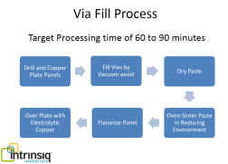
Now, for the exciting part, there are two distinct advantages for PCB manufacturing with this product. First, because it is run with commercially available equipment, as seen in the process flow diagram, the capital investment needed to offer copper-filled via technology is significantly reduced. Many printed circuit board manufacturers are not able to offer the copper-filled via option due to the cost of plating equipment and chemistries. The barrier to entry for these PCB manufactures will be eliminated.

The second exciting benefit to this technology is the process time requirement. Solid copper-plated vias typically require 4 to 6 hours of plating time by the manufacturer, along with the specialized equipment and chemistry. This new product will enable PCB manufacturers to produce copper-filled vias in 60-90 minutes. A shortened cycle time will have benefits in lead-time and processing costs.

Via Fill Process Intrinsiq

Product release for this screen printable paste is currently scheduled for the end of 2016. Throughout this year, pilot programs will be released, further testing completed and reliability data gathered.

Product development, an interesting process

Nano copper inks and pastes are typically sintered photonically with broadband (xenon) flash or near IR laser. Because the copper cladding is too thermally conductive to allow complete sintering and high power lasers are a barrier to entry due to cost and complexity, an oven solution was sought to keep the process compatible with existing technology. Heller Industries manufacturers a formic acid environment convection oven to be used for flux-less reflow. This was determined to be the perfect environment to sinter nano copper without oxidation. Nano copper paste can be completely sintered in 40 minutes or less.

The process development for this product has had several iterations. The initial proof of concept was to deposit paste into mechanically drilled blind vias using a vacuum bag to help fill the holes. Those initial coupons were plated and etched prior to filling to allow for laser sintering. As the development progressed, the testing moved to copper clad PCB’s with mechanical blind vias. The panels were electroless copper plated then electroplated to simulate actual via filling requirements. Unfortunately, the thermal conductivity of the copper foil prevented the ability to sinter the copper paste. Research then pointed to thermal sintering in a formic acid environment.

As the development process continued, it was determined that the extended time necessary for formic acid sintering at 250C destroyed the PCB laminate. Moving forward, other nano additives were included in the formulation to lower the temperature requirement to 225C. This formulation and temperature sintered the vias completely in 60 minutes.

The next phase in the development process was to screen print trace patterns on FR-4 to be sintered alongside the via filled coupons. These samples were used to calculate bulk resistivity as compared to copper. Typical measurements were 6X to 8X that of bulk copper. Typical epoxy-based conductive via fills are in the 20X to 50X range.

Today’s product

Moving forward, additional product development was undertaken resulting in the current formulation, which allows the sintering temperature to be reduced to 190C. The paste is sintered to pure copper in only 40 minutes in the Heller conveyor oven. Samples of this formulation were via filled using the vacuum bag technique, on copper clad panels, with copper plated blind vias. The panels were Heller sintered, planarized, over-plated and solder floated. Samples were then subjected to IPC standard reliability testing parameters. Each sample was floated at 288C, held at temperature for 10 seconds, cooled, and refloated 4 times.   The vias survived 5 solder float procedures.

It is always exciting to learn about the new developments in products and processes for the PCB industry. In this case, incorporating nano copper inks and pastes into standard printed circuit board manufacturing techniques will allow manufacturers to offer a solid copper-via option to their customers without significant capital investment in specialized plating equipment.

Please contact us for more information.      http://www.omnipcb.com         tarad@omnipcb.com


Tips for Time Critical PCB’s

Can you relate to this common scenario? A quotation is received for the fabrication of three different PCB part numbers and a purchase order is placed for delivery in five days, on a time-critical project.

A few hours later, the dreaded email is received. There are questions regarding the design that are putting the project on hold. It takes a day, or possibly two, to coordinate the resolution of the questions between your customer, the PCB designer and the fabricator.

Next, you are informed that the delivery date for the PCB’s is pushed out for the two day delay in answering questions. Ugh! Now the schedule has to be adjusted, the components you paid a premium for will be sitting there waiting for the boards, and your customer is NOT happy.

This scenario occurs time and time again. Approximately 90% of designs that go through CAD/CAM at a PCB fabricator have questions that must be answered before the fabricator can start the board manufacturing. Some questions are minor and can be answered quickly; others can require a partial or complete redesign of the PCB.

Elizabeth Foradori and I sat down to discuss our thoughts and ideas on how to best work with PCB fabricators to reduce the likelihood of any delays during time-critical development of a new product.   Chapters could be written on this topic, but our hope is that these ideas provide a basis to encourage discussion early in the design process.

Prior to placing a purchase order:

Research and select your printed circuit board fabricator early in the process: If the design is going to be a standard design, on common material and fit neatly into any manufacturer’s “standard capabilities”, that makes things much easier. But, if the new design is going to be pushing the limits of standard technology in any way – microvias, fine line, tight pitch or tight tolerance, selective surface finish, exotic materials, rigid-flex – selecting a supplier early in the process, whose capabilities match the technology needed, will ensure that the design can be manufactured quickly once you are ready to release the files.

Involve the fabricator early in the design process: Ask questions. Talk to your supplier frequently during the design of the PCB. They encourage questions and are happy to make recommendations. Once the fabricator understands what you are trying to accomplish, they can make recommendations that will ensure that the design is manufacturable.   As a final step, or even an intermediate step during the design process, ask your fabricator to run a design rule check based on your files. This may not catch every issue and eliminate all engineering questions at the CAD/CAM stage, but it will catch the major issues that would require lengthy redesign once a project is released.

Verify that material is available and will be in stock when the design is complete:   Fabricators do try to stock the common materials and even small quantities of the less common materials to avoid delays. Unfortunately, they cannot stock all materials. Once the stack-up is finalized, ask the fabricator if this is material that will be in stock. If not, work with your supplier to pre-order the material to have in-house when you are ready to release the design. Some fabricators will secure material based on a simple email authorization; others will require a purchase order. Either way, planning for material to be in stock when the design is complete can save anywhere from five days to six weeks.

Once a purchase order is placed:

Send complete files: Review the files being submitted with the purchase order to ensure they are complete. Is the net list included? Are the fab notes complete, confirming any quality requirements, material specifications, and surface finish requirements? Do the fab notes match the gerber data?   These are all very common reasons that files are placed on engineering hold.

When you receive questions from the CAD/CAM tooling group, ask if this includes all questions associated with the design. Sometimes two different engineers may be working on the same design to meet an expedited delivery and both may have questions in their portion of the process. Other times, when the initial issues are encountered, the job is set aside only to find additional issues when work is resumed. The process can be streamlined by taking all questions to your designer or your end customer at one time.

If questions are fairly involved, it is always best to try to schedule a conference call between your fabricator, your designer or end customer and yourself to resolve the issue as quickly as possible. Email offers a great documentation trail for any changes, but can drag the process out longer than necessary. If communicating via conference call, ensure that someone is responsible for documenting the discussion and sending that to all parties involved.

Once the questions are answered, follow up with your supplier to confirm that the questions involved in the tooling process have not impacted your delivery schedule. Delays of a few hours are usually absorbed into the initial lead-time. Longer delays can impact delivery. PCB fabricators are typically very good about notifying customers of any changes in delivery date due to engineering questions, but it is always a good practice to ask. You don’t want to be surprised on the day you are expecting your printed circuit boards.

In summary, communication with your supplier is the best way to reduce the cycle time needed for fabrication of time-critical, new printed circuit board designs. Ask for recommendations during the design phase to ensure the design is manufacturable, verify that material will be available when the design is released, and if there are engineering questions, and communicate quickly to have those resolved.   Take advantage of the fabricators expertise and ask questions!

Contact us for further information!  www.omnipcb.com

Acceptance Criteria for Cap Plating of Filled Vias

We are periodically asked about the acceptance criteria for cap plating of filled holes.

Today’s engineering tip gives the acceptance criteria per IPC A-600.

Target condition:  Copper surface is planar with no protrusion (bump) and/or depression (dimple)

Acceptable condition – Class 1,2, and 3:
• Separation of copper cap to fill material
• No separation of the cap plating to underlying plating
• Cap protrusion (bump) and/or depression (dimple) meets the dimensional requirements in IPC 6012
• Fill material within the blind via shall be planar with the surface within +/- .076 mm (.003”) unless otherwise specified
• When cap plating is specified, fill material within the blind via shall meet the dimple/bump requirements of IPC 6012
• No voids in the cap plating over the resin fill

Please contact us if you have any questions!

Remember, designing and purchasing printed circuit boards should not be difficult!

Sub 1 Mil Line and Space

Breakthrough in fine line metallization

IC packaging and high end applications are driving the need for finer lines.  Conventional (subtractive etch) processing has a hard barrier at 25 micron resolution.  Omni PCB is now working with an additive approach that can achieve fine lines and thin copper, less than 10 microns.

Capabilities: 

  • ·         Fine line ( 5 microns) to wide line (250 microns)
  • ·         10 micron vias plated through
  • ·         Copper  thickness from .1 to 10.0 microns
  • ·         Substrates with thickness of 50,25, 12 microns or less
  • ·         Single circuits or panels of up to 18” x 24”
  • ·         Coat pre-drilled via walls


 What is it? 

  • ·         Truly Additive Metalization
  • ·         Print-and-Plate Copper Circuit Patterns
  • ·         On Thin Substrates
  • ·         True Adhesiveless Copper
  • ·         Fine Lines and Spaces
  • ·         Ultrathin Copper Capability
  • ·         Copper Thickness Made To Order

Contact us to learn more!!!    

http://www.omnipwb.com

Tara Dunn  507-332-9932  tarad@omnipcb.com  

Elizabeth Foradori  856-384-1300  elizabeth@omnipwb.com


Zeta Materials

Zeta Materials ~ This changes everything!

Following is a brief overview of  Zeta materials.   If you have a need for a thin, fine line application or are looking for a solution to a pad cratering problem, contact us to learn more!

 First Imagine:  8 layers of Zeta Lam in a 10 layer PCB ~ Total thickness – 16 mils. 

Enabling next generation HDI.

The power of 50 microns at only 12 microns – harness the power of thicker boards in ultra-thin boards that are only 25% as thick.

Zeta glass free films provide less than 25 micron dielectric in a multilayer HDI package.
  •  Dk – Cap – 2.97 @ 10 GHz     Lam – 3.15 @ 10 GHz
  •  Df –  Cap – .006 @ 10GHz      Lam – .010 @ 10 GHz
  • Decomposition Temp – Cap > 500 C      Lam – 400 C
  • Glass Transition Temp –  180 C
  • Thermal Conductivity – Cap – .043 W/mK     Lam – .51 W/Mk
  • Low Z-Axis CTE
  • Low Moisture Absorption
  • Dimensionally Stable

Eliminates Pad Cratering

Pad cratering is a mechanically induced fracture in the resin between copper foil and the outermost layer of fiberglass of a PCB.  The pad remains connected to the component leaving a “crater” on the surface of the PCB.

Zeta Cap virtually eliminates pad cratering.  Once laminated to the surface as a cap, the resilient layer acts as a shock absorber to prevent fracture formation.   This material is more flexible than rigid, but 3 times stronger than flex.   Contact us for more detailed information!

Products:

Zeta Cap:  Next generation C-stage dielectric film designed to interface between the copper pad and the rest of the PCB.  It’s unique liquid-cast polyimide film is bonded to copper foil.  The ultra-thin film lays-up like a copper foil on prepreg in a conventional PCB manufacturing process.

Zeta Lam: Next generation dielectric film that facilities HDI build structures and minimizes the risk of pad cratering.  LAM is formed by laminating Zeta CAP to Zeta BOND, a proprietary B stage bonding film.  It acts like a glass dielectric in a conventional prepreg but is ultra-thin with guaranteed copper-to-copper Z axis standoff as thin as 12 micons.  It’s low CTE, High Tg and high Td make it suitable for sequential lamination cycles and higher-layer HDI structures.

Zeta Bond:  B-stage bonding film capable of filling circuits and vias.

If you are facing challenges with your new generation HDI designs or have pad cratering issues, please contact us for more information!

 www.omnipcb.com

 Click HERE to email us for additional information.

PCB Design Questions

We get asked many PCB Design questions and noticed a trend in the questions we are asked about most frequently.  Do you have the same questions?  Please give us a call if we can help! 


Annular Ring/Pad size That portion of conductive material completely surrounding a hole.  This can be particularly confusing when working with IPC Class 2 vs. Class 3 and with space constraints. 


Aspect Ratio A ratio of the PCB board thickness to the diameter of the smallest hole.  This can be confusing when moving to a micro via construction.


Blind Via A conductive surface hole that connects an outer layer with an inner layer of a multi layer board without penetrating the entire board.


Buried Via – A via hole that connects two or more inner layers but does not extend to either surface of a printed board.


Micro via – Usually defined as a conductive hole with a diameter of 0.006″ or less that connects layers of a multilayer PCB. Often used to refer to any small geometry connecting hole, that is beyond the traditional mechanical drilling capabilities.  Micro via designs are increasing.  There is a whole new set of design rules and options available often with significant cost differences.


Controlled Impedance –  The matching of substrate material properties with trace dimensions and locations to create specific electric impedance as seen by a signal on the trace.  It is always a good idea to have your supplier verify this calculation for you early in your design process. 


Wrap Plating – Copper plating from the hole that wraps around the surface to increase via in pad reliability in the field.


HDI (High Density Interconnect) – Ultra fine-geometry multi layer PCB constructed with conductive surface micro via connections between layers. These boards also usually include buried and/or blind vias and are made by sequential lamination. Again, design rules can be confusing and different design approaches can have a significant impact on cost.


Interconnect Stress Test– The IST system is designed to quantify the ability of the total interconnect to withstand thermal and mechanical strains.  The test applies stress from the “as manufactured” state until the product reaches the point of interconnect failure.   


Back Drilling – The process of removing the unused portion “stub” of vias by drilling a larger hole from one or both sides after the plating processes. This is typically required in very high speed applications (10GHz or greater) to minimize the parasitic effects of the via stubs.


As always, please contact us for more information.  Designing and purchasing printed circuit boards should not be difficult!


WWW.OMNIPCB.COM

Micro Vias: The Basics

For those of you wondering “what is all the fuss about micro vias”, we have put together a short list of “the basics”.

What is a Micro Via?

A blind connection between two layers, usually adjacent, hole of .006″ or less, typically drilled with laser technology.

Why use Micro Via Technology?

  • Fine pitch devices
  • Limited real estate
  • High levels of interconnect
  • Reduced hole sizes
  • Reduced pad sizes
  • More direct signal path
  • Improved reliability by changing technology rather than pushing older technology limits

Types of Micro Via constructions:

Staggered:  Micro Vias are staggered, or offset, from layer to layer

Stacked:  Micro Vias are “stacked” on top of each other.  This allows greater design density

Skip:  Micro Vias from L1-L3 rather than L1-L2, L2-L3.  This reduces the number of required lamination cycles

ELIC:  Every layer Inter Connect

Benefits of Micro Via Construction:

  • Smaller PCB’s
  • Improved electrical performance
  • Improved reliability
  • Thinner construction
  • Lighter weight
  • Space savings
  • RF line termination
  • Lower layer count

As always, please contact us for more information.  Designing and purchasing printed circuit boards should not be difficult!

WWW.OMNIPCB.COM

ENEPIG Solderable Finish

ENEPIG:  Is this the universal finish?

We are asked quite often about the availability and benefits of ENEPIG.  As I was reading a recent article in PCB007 by Mike Carano that discusses various solderable surface finishes, I thought our customers would appreciate the information presented and wanted to specifically highlight the information presented on ENEPIG.  A link the entire article is attached below.

ENEPIG 

If hyper-corrosion and black pad are of concern, ENEPIG is a solution. Here, the gold deposits onto the palladium, not the nickel. There is no hyper-corrosion effect as there is with gold over nickel. ENEPIG is often referred to as the “universal finish,” capable of good solderability and wire bondability. However, one must look at this more expensive finish in the context of the circuit board and its intended use/environment.

One area in which ENEPIG has found use is the IC substrate market. ENEPIG can function as one finish for both wire bonding and solder attachment. While it is true that ENIG can perform the same functions, ENEPIG is more robust with respect to gold wire bonding. Typical plating thicknesses for this three-metal-stack over copper are as follows:

  • Au Layer: 0.03-0.06 micron;
  • Pd Layer: 0.10-0.50  micron; and
  • Ni Layer: 3.0-6.0 micron.

 The nickel present on the surface benefits from a Pd or Au protective layer to improve solderability by reducing brittleness and oxidation of the solder joint. The basic idea is to achieve improved solderability and wire bonding at reduced palladium and gold thicknesses. For the majority of ENEPIG systems, the palladium is deposited as an electroless reaction. Commercial palladium systems are based on one of two reducing agents, hypophosphite or formate. The former will co-deposit 1-6% phosphorous into the deposit, while the latter is nearly 100% pure palladium.

There is no industry specification for ENEPIG, although one is under development. A key component of any specification is the verification of both solderability and wire bondability at varying palladium thicknesses. Again, lower thicknesses of both palladium and gold will enhance the economic viability of this finish as long as the solderability/wire bonding requirements are met.

Mike Carano’s full article discussing factors to be considered when choosing a solderable surface finish,  a review of the latest solderable finishes and special considerations when using these finishes can be found at:  http://www.pcb007.com/pages/zone.cgi?artcatid=0&a=85243&artid=85243&pg=1.

Mike will be joining us for a PCB Coffee Talk webinar session later this year discussing surface finishes.